3. Parts
- AD9833 DDS Module 25 MHz Clock
with AD8051 Output Amplifier and MCP41010 Digital Potentiometer - ESP32 Microcontroller DoIt DevKit V1
- LC Display I2C 4 x 20
- Rotary Encoder with axial Pushbutton
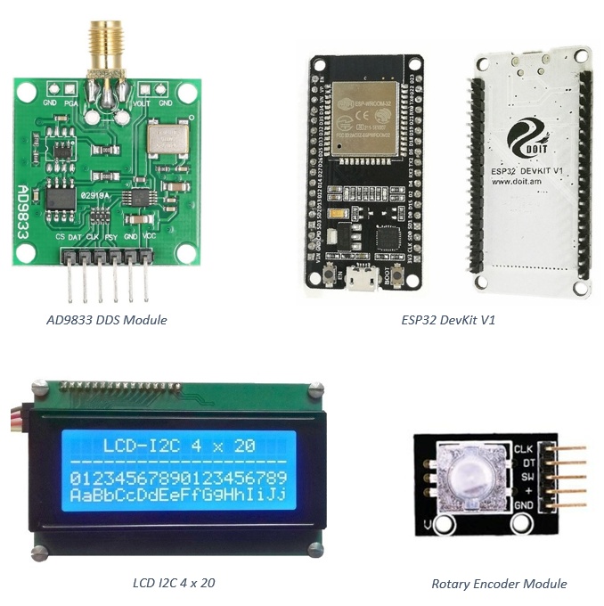
The function generator is based on Direct Digital Synthesis (DDS) realized with an AD9833 module which also incorporates an output amplifier AD8051 whose output amplitude is controlled by a digital potentiometer MCP41010.
An ESP32 microcontroller controls all the functions of the DDS module and also realizes the user interface comprising an I2C LCD and a rotary encoder with axial pushbutton.
The various functions of the generator are choosen by clockwise (cw) or counterclockwise (ccw) rotating the rotary encoders shaft and by clicking (click, or longclick) its pusbutton.
                     USB                             .----------------.
               .-----I I-----.                  27 --o CLK            |
               o 3V3 `¨´ Vin o-- LCD Vcc        26 --o DT   Rotary    |
               o GND     GND o-- LCD GND        25 --o SW   Encoder   |
               o 15       13 o                3.3V --o +    with      |
     DPOT CS --o 2        12 o                 GND --o GND  Pusbutton |
               o 4        14 o                       `----------------´
               o RX2      27 o                       .--------------------.
               o TX2      26 o                   2 --o CS   DDS           |
   AD9833 CS --o 5        25 o                  23 --o DAT  Breakout Board|
  AD9833 CLK --o 18       33 o                  18 --o CLK  with          |
               o 19       32 o                   5 --o FSY  AD9833 DDS    |
     LCD SDA --o 21       35 o                 GND --o GND  MCP41010 DPOT |
               o RX0      34 o                3.3V --o Vcc  AD8051 OPAMP  |
               o TX0      VN o                       `--------------------´
     LCD SCL --o 22       VP o                       .--------------.
  AD9833 DAT --o 23       EN o                 GND --o GND  4 x 20  |
               `-------------´                 Vin --o VCC  Liquid  |
               ESP32 DevKit V1                  21 --o SDA  Crystal |
                                                22 --o SCL  Display |
                                                     `--------------´
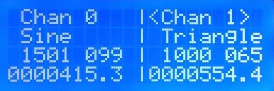
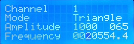
On power up Screen-0 is displayed. The settings of both channels are shown. The active channel is marked, here as ⟨Chan 0⟩. We see the selected wave forms, the settings of the digital potentiometer and and the actual frequencies of each channel.
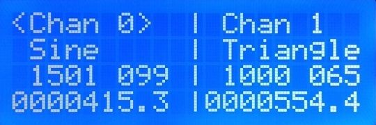
The values of both channels can be set independently. The set values are not remembered between power ups. That is left for further enhacement and could be done by storing the settings in ESP32 flash memory.
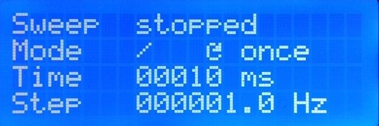
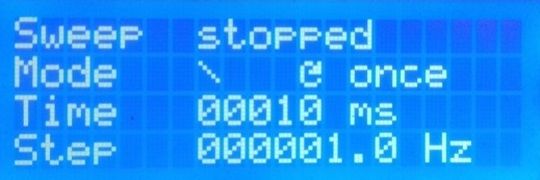
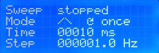
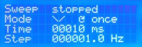
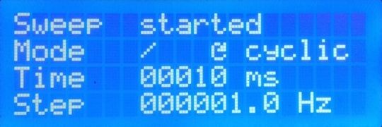
The sweep frequency starts at the frequency set for channel 0 and stops at the frequency set for channel 1. The possible modes are shown below.
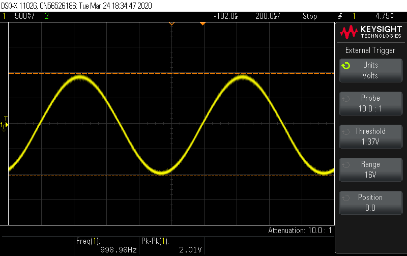
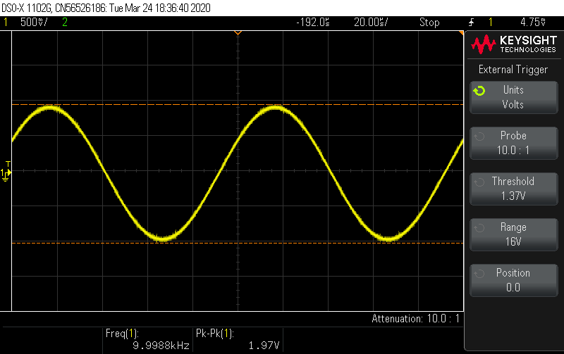
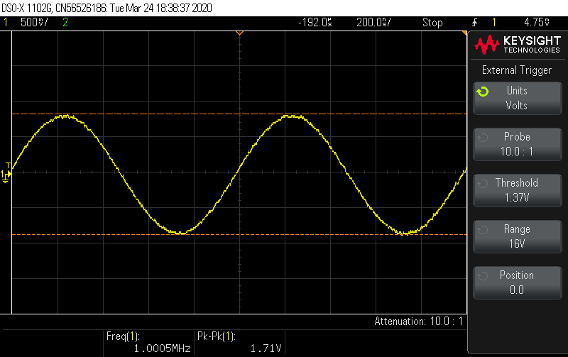
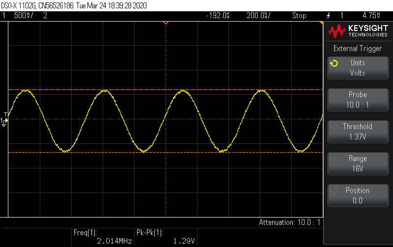
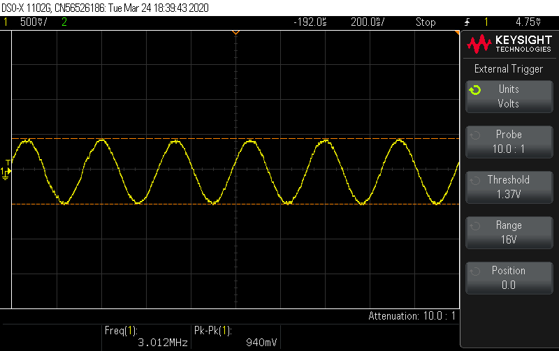
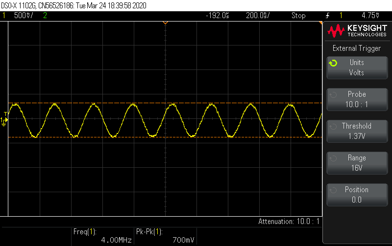
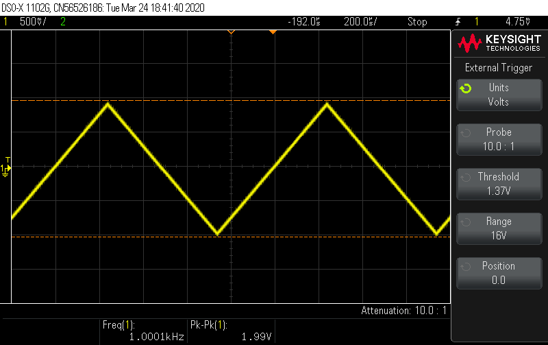
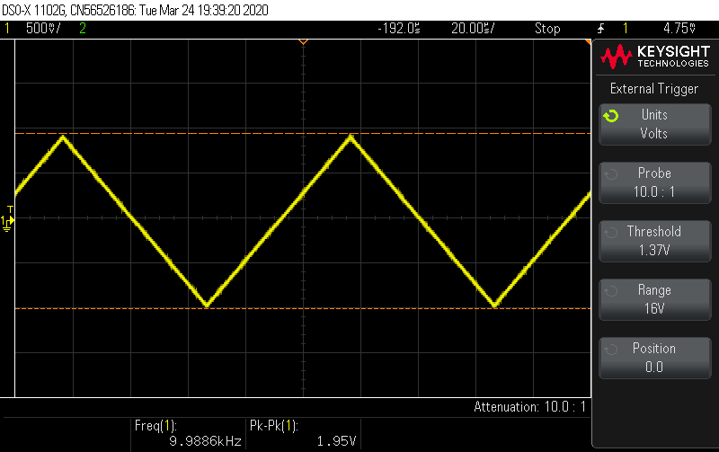
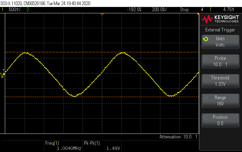
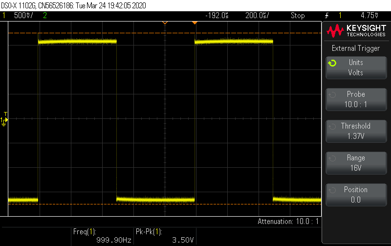
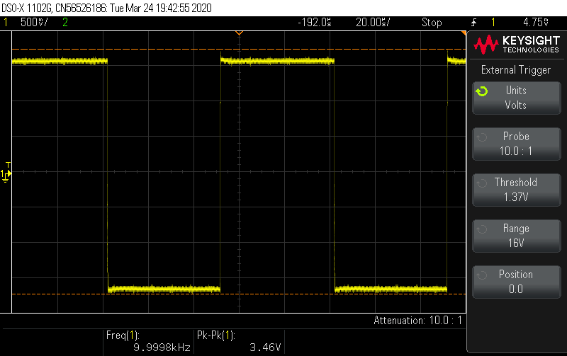
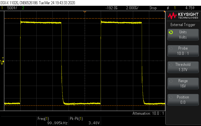
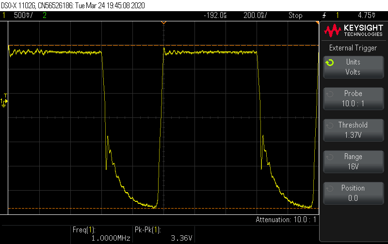
Waveform pictures are all taken with amplitude set to 133 units of the digital potentiometer, corresponding to 2000 mVpp. We see clearly the decreasing amplitude and degradation of the waveform at higher frequencies.


The statechart, created with the free tool YAKINDU™, shows the basic operation of the frequency generator.
Rotating the shaft of the rotary encoder cycles through the 4 screens.
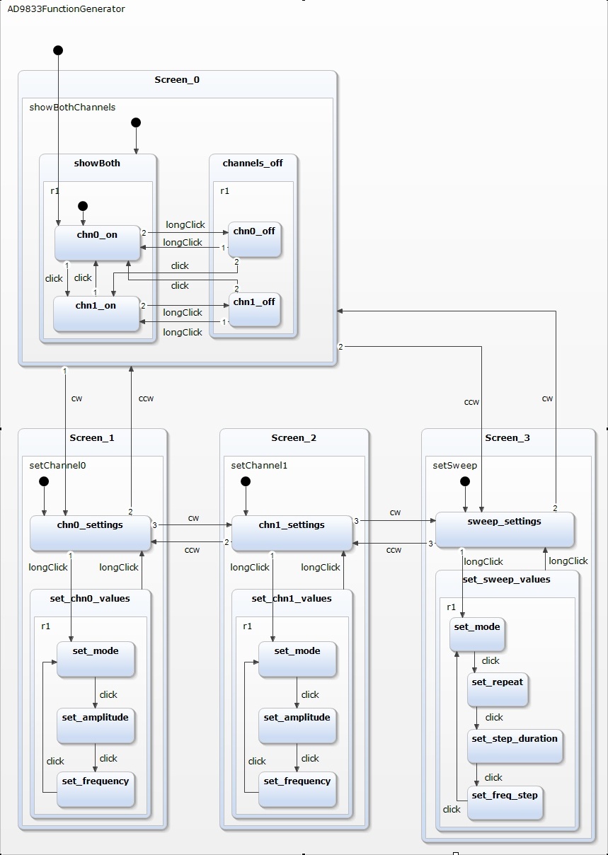
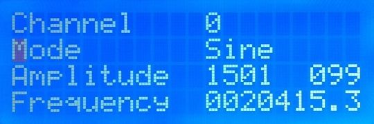
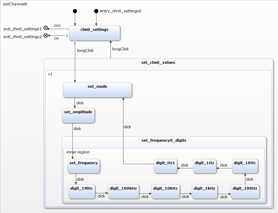
The next statechart shows the settings of channel 0 in more detail. The individual digits of the frequency are reached by clicking and then changing value by rotating the rotary encoders shaft.
Duration and frequency step for sweep mode are set in an analog way.
My programming environment is not the native Arduino™ IDE but PlatformIO™ on top of Microsoft's Visual Studio Code™. This combination offers many advantages and allows a much better structuring of the code into several modules especially when we adopt The Object Oriented way.
The code below shows the main program. It mostly consists of comments. The setup() function in turn calls setup() of the classes AD9833FuncGen and ControlKnob and initializes the LCD. Astonishingly the main loop() consists of a single line namely the call of the loop() function of the class ControlKnob. This class realizes the Finite State Machine and handles the 4 actions onClick(), onLongClick(), onCW() and onCCW().
  #include "AD9833FunctionGenerator.h"

  hw_timer_t * timer = NULL;
  volatile SemaphoreHandle_t timerSemaphore;
  portMUX_TYPE timerMux = portMUX_INITIALIZER_UNLOCKED;

  void IRAM_ATTR onTimer()
  {
    //portENTER_CRITICAL_ISR(&timerMux);
    // Critical code here
    //portEXIT_CRITICAL_ISR(&timerMux);
    // Give a semaphore that we can check in the loop
    xSemaphoreGiveFromISR(timerSemaphore, NULL);
  }

  void setup()
  {
    Serial.begin(COMPORT_SPEED);

    ad9833FuncGen.setup();

    lcd.init();
    lcd.createChar(0, topLine);
    lcd.createChar(1, backslash);
    lcd.createChar(2, roundArrow);
    lcd.backlight();
    lcd.clear();
    lcd.print("   LCD-I2C 4 x 20   "); lcd.setCursor(0,1);
    lcd.print("--------------------"); lcd.setCursor(0,2);
    lcd.print("01234567890123456789"); lcd.setCursor(0,3);
    lcd.print("AaBbCcDdEeFfGgHhIiJj");
    lcd.display();

    cntrlKnob.setup(); // Shows initial values on LCD

    timerSemaphore = xSemaphoreCreateBinary();
    timer = timerBegin(0, 8000, true);  // Use 1st timer of 4 (counted from zero).
                                        // Set 80 divider for prescaler (see ESP32 Technical Reference Manual for more info)
                                        // 80   --> clock = 1.0 usec
                                        // 8000 --> clock = 0.1 msec


    timerAttachInterrupt(timer, &onTimer, true);  // Attach onTimer function to our timer
                                                  // Set alarm to call onTimer function every 0.1 ms
                                                  // Repeat the alarm (third parameter)
  }

  void loop()
  {
    cntrlKnob.loop();  // All the functionallity is handled in the control knobs loop
  }
Interested? Please download the entire program code. The zip-file contains the complete PlatformIO project.
My programming environment is not the native Arduino™ IDE but PlatformIO™ on top of Microsoft's Visual Studio Code™. This combination offers many advantages and allows a much better structuring of the code into several modules especially when we adopt The Object Oriented way.