While browsing the extensive Technical Reference
Manual
for the ESP32, I came across the description of the Cosine Wave Generator.
The many registers and cryptic designators soon put me off, but I
thought surely someone had already done the hard work. The works of
Krzysztof
and Helmut
were quickly found and these are therefore the basis for my contribution.
I packed up all the ideas and designed the CosineWaveGenerator (CWG) class
and a simple command line interface (CLI) to explore the generator's
capabilities.
2. Specification
Output channels GPIO25 and GPIO26
Common frequency for both channels 15 .. 1'000'000 Hz (usable up to 500'000)
Mode 0 .. 3 per channel |\/| |/\| /\ \/
Amplitude 0 .. 3 per channel
Offset 0 .. 255 per channel
3. Some Formulas
The frequency of the CWG depends on the operating frequency of
the microcontroller and the contents of two registers. The common
output frequency of both DAC channels is given by the formula:
  freq = dig_clk_rtc_freq / (1 + RTC_CNTL_CK8M_DIV_SEL) * SENS_SAR_SW_FSTEP / 65536
  dig_clk_rtc_freq = 8'000'000 Hz (assumed operating freq, no need to know it exactly, see below)
  RTC_CNTL_CK8M_DIV_SEL = 0..7
  SENS_SAR_SW_FSTEP     = 1..65535 (0x0001..0xffff)

  If we set
      RTC_CNTL_CK8M_DIV_SEL = 0
      SENS_SAR_SW_FSTEP     = 1
  we get
      f0 = dig_clk_rtc_freq / 65536
  and with
      dig_clk_rtc_freq = 8000000
  we find
       f0 = 122.0703125
If we measure another frequency, the operating frequency of our microcontroller
is not exactly 8 MHz. Thats why we must first set the reference frequency f0 to
our measured value.
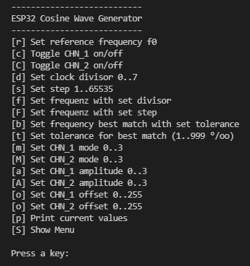
4. User interface (CLI) and Operation
The user interface is a simple command line interface. The menu items are
self-explanatory.
Command line interface
If we set a frequency of 200 Hz by pressing "b" and entering the value,
we get the following output:
Setting 200 Hz with tolerance 10 ‰
The exact Frequency of 200 Hz cannot be set and the specified tolerance
of 10 ‰ cannot be kept. Therefore, the best approximation is set
and the found values are displayed.
Now we change the tolerance by pressing "t" and entering 20 followed by pressing
"b" again and entering 200.
Setting 200 Hz with tolerance 20 ‰
We see that the best approximation is 203 Hz and that this frequency is
also within the given tolerance.
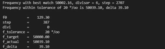
Now we set a higher frequency, namely 50000 Hz. Afterwards we also press "p"
to output the set values.
Setting 50000 Hz and pressing "p"
We see that with a divisor of 6, a deviation of only 2 HZ can be achieved.
However, because a tolerance of 20% is acceptable, the smallest divisor is
used to obtain the smoothest possible curve shape.
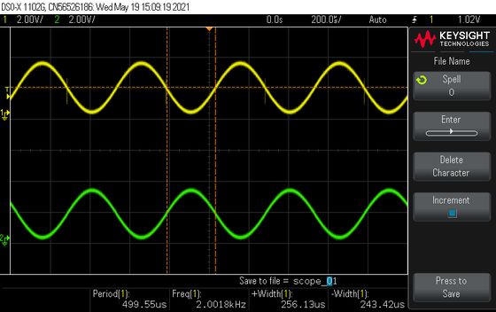
Let's have a look at the different modes of the two output channels.
CHN_1 in Mode 0, CHN_2 in Mode 1"
For the hobbyist, the two sinusoidal modes will probably be most useful.
CHN_1 in Mode 2, CHN_2 in Mode 3"
4. Program Code
The main program, is quite simple. Here only the menu structure and the
main loop is shown, which consists only of the call to doMenu() if a
character was entered on the serial interface.
  typedef struct { const char key; const char *txt; void (&action)(); } MenuItem;

  MenuItem menu[] =
  {
    { 'r', "[r] Set reference frequency f0",    setReferenceFrequency },
    { 'c', "[c] Toggle CHN_1 on/off",           toggleChannel1 },
    { 'C', "[C] Toggle CHN_2 on/off",           toggleChannel2 },
    { 'd', "[d] Set clock divisor 0..7",        setDivisor },
    { 's', "[s] Set step 1..65535",             setStep },
    { 'f', "[f] Set frequenz with set divisor", setFrequencyWithSetDivisor },
    { 'F', "[F] Set frequenz with set step",    setFrequencyWithSetStep },
    { 'b', "[b] Set frequency best match with set tolerance", setFrequencyBestMatch },
    { 't', "[t] Set tolerance for best match (1..999 °/oo)", setTolerance },
    { 'm', "[m] Set CHN_1 mode 0..3",           setMode1 },
    { 'M', "[M] Set CHN_2 mode 0..3",           setMode2 },
    { 'a', "[a] Set CHN_1 amplitude 0..3",      setScale1 },
    { 'A', "[A] Set CHN_2 amplitude 0..3",      setScale2 },
    { 'o', "[o] Set CHN_1 offset 0..255",       setOffset1 },
    { 'O', "[o] Set CHN_2 offset 0..255",       setOffset2 },
    { 'p', "[p] Print current values",          printCurrentValues },
    { 'S', "[S] Show Menu",                     showMenu }
  };
  constexpr uint8_t nbrMenuItems = sizeof(menu) / sizeof(menu[0]);

  void doMenu()
  {
    char key = Serial.read();
    for (int i = 0; i < nbrMenuItems; i++)
    {
      if (key == menu[i].key)
      {
        menu[i].action();
        break;
      }
    }
  }

  void setup()
  {
    Serial.begin(115200);
    showMenu();
    cwGen.enable(DAC_CHANNEL_1);
    cwGen.enable(DAC_CHANNEL_2);
  }

  void loop()
  {
    if(Serial.available())
    {
      doMenu();
    }
  }
Interested? Please download the entire program code. The zip-file
contains the complete PlatformIO project.