2. Parts
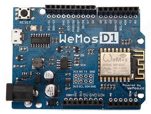
- Wemos D1 R2 board
- Pushbutton
- Oscilloscope
Actually I wanted to implement the Arduino project Timer1 Sqare Wave Generator on the ESP8266. I soon realized that this controller had a completely different architecture and that a one-to-one implementation was not possible. But my efforts were not in vain, because I thereby discovered the I2S subsystem of the ESP8266. I had heard of this interface for exchanging digital audio data between ICs, but had never looked into it in detail. A look at it could certainly be enlightening.
The I2S subsystem is not described in detail in the documentation of the chip manufacturer Espressif. Fortunately, however, there are hobbyists who kindly make their findings or entire projects available to the general public on the Internet.
    WEMOS D1 R2            to scope
  ----------------.
                  |
                  |
     GPIO_15 / D8 o--> I2S_BCK   bit clock
                  |
      GPIO_2 / D4 o--> I2S_WS   word select
                  |
      GPIO_3 / RX o--> I2S_DATA  serial data
                  |
                  |    _I_
      GPIO_0 / D3 o----o o----/ GND
                  |
  ----------------´
The I2S interface is a 3-wire interface developed by Philips. The original names of the 3 signals are SDK (serial clock), WS ( word select) and SD (serial data). Other manufacturers use other designations, e.g. for SDK also BCLK (bit clock) or SCLK (serial clock). WS is also called LRCLK (left/right clock) or Frame Clock and SD can also be called SDATA, SDOUT or DACDAT.
Normally 16 bits per sample are transmitted for the right and for the left audio channel. So a sample of a stereophonic audio signal can be packed into a 32-bit double word. The differentiation between right and left channel is done with the help of the word-select signal. From this it follows that the frequency of the WS signal is 1/32 of the bit-clock signal.
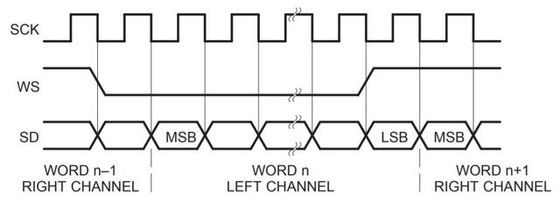
From the diagram above we see that the WS signal transitions one clock period
before the completion of a data word. One word (16 bit) of a data double
word (32 bit) represents the right channel and is transmitted on WS = 1 with MSB
first. The other word represents the left channel and is transmitted on WS = 0
The usual sampling rate for audio data is 44100 Hz which results in a
bit rate of 1'411'200 Hz.
On the ESP8266 the I2S bitclock and wordselect signals are derived from an internal base frequency I2SBASEFREQ of 160MHz which is divided by 32 to get f_baseclk of 5MHz. Two further divisors div1 and div2 in the range 2..63 then determine the frequency of the wordselect signal. The internal hardware ensures that the frequency of the bitclock is 32 times the frequency of the wordselect.
Therefore the following formulas apply:
  f_baseclk = I2SBASEFREQ / 32 = 5 MHz

               f_baseclk
  f_ws      = -----------  with div1, div2 = 2..63
              div1 * div2
The difficulty now is to determine the two integer divisors in such a way that
the desired sampling rate is approximated as closely as possible.First I want to set a sampling rate of 44100 Hz and check, how exactly the desired frequency is reached with i2s_setRate(44100).
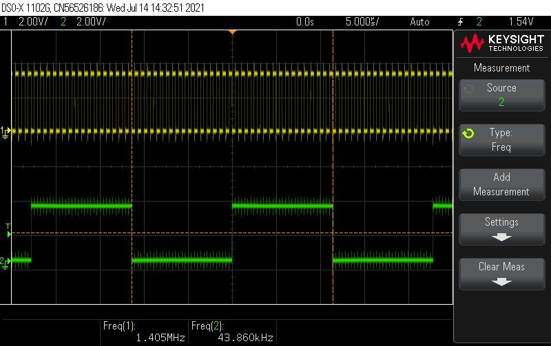

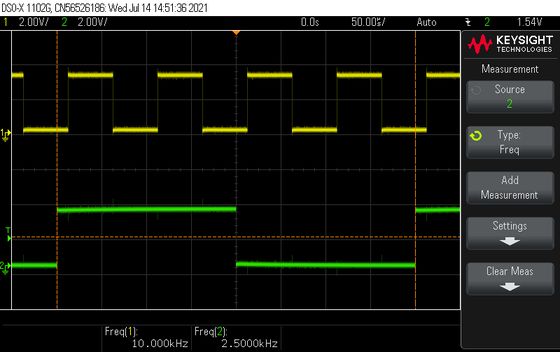
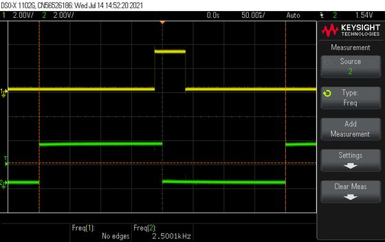
The oscilloscope shows on channel 1 the bit clock and on channel 2 the
word select signal (sampling signal).
The exact frequencies would be 44100 and 1411200 Hz but the oscilloscope
and the display on the monitor show that the set frequency is 43859.648,
which corresponds to a bit rate of 1403509 Hz. We also see that the exact
divisor would be 113.379. Unfortunately, the next integer 113 is a prime
number that cannot be decomposed into a product of two numbers < 63.
The second best number is then 114, which makes the number pairs (57, 2),
(38, 3), (19, 6) possible as divisors.
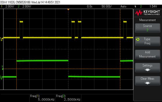
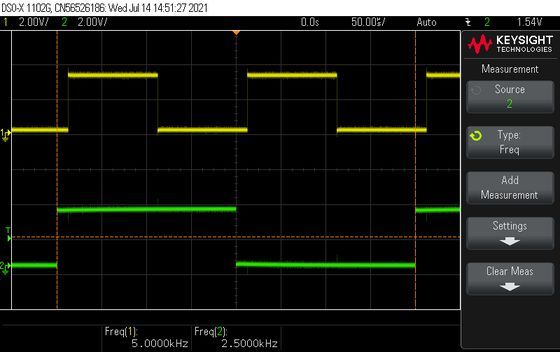
For the further experiments I set the sampling rate to 2500 Hz with i2s_set_rate(2500).
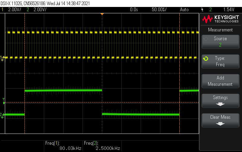

As expected, this frequency can be set precisely. The divisor is 2000, which is achieved with the number pair (50, 40). The bit rate (80 kHz) is 32 times the sampling rate (2.5 kHz).
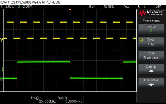
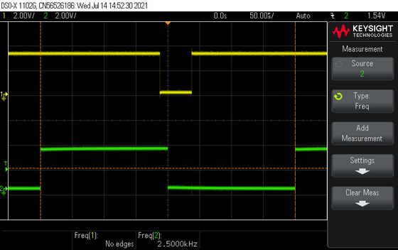
In the further experiments I show the I2S data output (RX) on channel 1 of the oscilloscope.
The function i2s_write_sample() writes a 32 bit double word to the output. As the I2S timing showed above, one word (16 bit) contains the information of the right stereo channel and the other word that of the left channel. The selection is done with the wordselect signal.
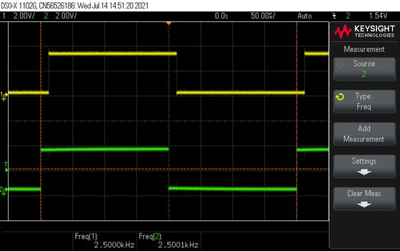
I want to find out in which word the bits of the left channel are packed and in which those of the right channel. For this I write the bit pattern 0b10000000000000001010000000000000 to the output. This means, in one channel 1 bit is set (high word) and in the other 2 (low word).
  uint32_t sample = 0b10000000000000001010000000000000;
  i2s_write_sample(sample);
Aha, ws=high selects the channel with 1 bit set, so the high word. This means that the information of the right channel is in the high word and that of the left channel in the low word.
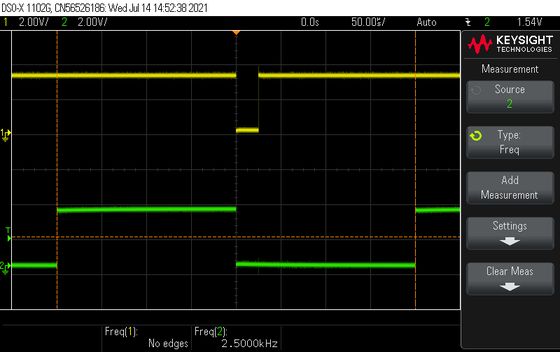
I could not use my preferred Command Line Interface (CLI) here, because RX of the serial port is used for the I2S data output. Therefore I only used a simple push button to scroll through the 10 predefined patterns. One click selects the next pattern, a long click the previous and a double click displays the current pattern.
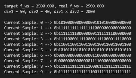
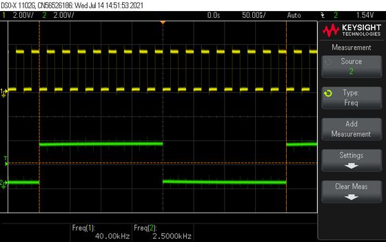
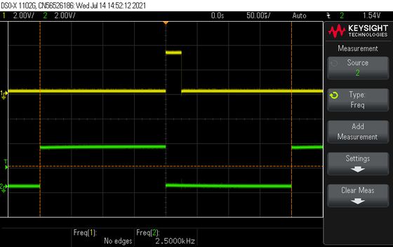
The remaining samples 1..9 are shown here without further comment.
The functionality for the push button is implemented in the ButtonDebounced class. It debounces the push button and implements the onClick(), onLongClick() and onDoubleClick() methods. The main loop then essentially just writes the sample to the I2S output and calls the button.loop().
  ButtonDebounced button(pinButton, nextSample, prevSample, showCurrent);
  bool done = false;

  void loop()
  {
    // delay(10000); return; // activate this line to investigate only the set frequencies
    if(!done)
    {
      Serial.println();
      Serial.println();
      findDivisors(div1xdiv2, div1, div2, zbest, diffbest);
      showValues();
      done = true;
    }

    i2s_write_sample(sample[currentSample].value); // write a doube word
    button.loop();
  }
Interested? Please download the entire program code. The zip-file contains the complete PlatformIO project.
My programming environment is not the native Arduino™ IDE but PlatformIO™ on top of Microsoft's Visual Studio Code™. This combination offers many advantages and allows a much better structuring of the code into several modules especially when we adopt The Object Oriented way.