2. Parts
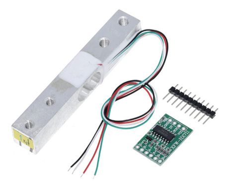
- Load cell 1kg
- HX711 ADC
- Arduino Uno
Because I have always been interested in sensors of all kinds, I wanted to
investigate these cheap load cells with the associated HX711 analog-to-digital
converter. Many others have done that before me and therefore there are some
Arduino libraries that can be used.
What bothered me about these solutions was that a calibration factor had to
be figured out. Because there is a linear relationship between the output
value of the ADC and the measured weight, it is possible to automatically
obtain the determining factors from two measurements with known weights.
                +------------------+
         red    o E+   HX711       |
  Load-  black  o E-           GND o --> GND    Arduino Uno
  cell   white  o A-           DT  o --> PIN 3
         green  o A+           SCK o --> PIN 2
                o B-           Vcc o --> 5V
                o B+               |
                +------------------+
The following relationship exists between the weight to be measured and the digital output value v of the HX711:
weight = m * v + b
We therefore only need to determine the two unknowns m and b. We do this by determining v0 with 0 load and vref with a reference weight wref., for example with the maximum permissible load.
Thus we obtain the two equations:
  0    = m * v0 + b
  wref = m * vref + b
Finally we get:
  m = wref / (vref - v0)
  b = -wref * v0 / (vref - v0)
  -------------------------------------
  weight = wref * (v - v0) / (vref - v0)
  -------------------------------------
If we consult the data sheet of the HX711, we see that neither I2C nor SPI but a proprietary protocol is used to read out the measured values. The measured value is available as 24-bit value in two's complement. So there are 3 bytes, of which the first read out byte contains the sign.
Two pins are used to read out the 24 bits, PD_SCK as clock input and DOUT as data output . As long as DOUT is HIGH, the measurement is not yet finished and PD_SCK should be LOW. As soon as DOUT goes LOW, the measured value is ready and with 24 positive pulses on PD_SCK the measured value can be read from DOUT bit by bit, MSB first. With 1, 2, or 3 additional positive pulses of PD_SCK, the readout is completed and at the same time channel and gain for the next measurement are set. The typical HIGH and LOW time of the PD_SCK pulses is 1 μs and should not be less than 0.2 μs.
So a byte can be read with the following method:
  uint8_t readByte(uint8_t dataPin, uint8_t clockPin, uint8_t bitOrder)
  {
    uint8_t value = 0;

    for (uint8_t i = 0; i < 8; ++i)
    {
      digitalWrite(clockPin, HIGH);
      delayMicroseconds(2);  // stretch pulse for safety
      if(bitOrder == LSBFIRST)
        value |= digitalRead(dataPin) << i;
      else
        value |= digitalRead(dataPin) << (7 - i);
      digitalWrite(clockPin, LOW);
      delayMicroseconds(2);  // stretch pulse for safety
    }
    return value;
  }
We call this method three times and store the result in an array of 3 bytes. We can pack the 3 bytes into an int32_t variable by shifting the first read byte 16 bits to the left, the second byte 8 bits and applying each time a bitwise OR operation. The last byte is only ORed without shifting.
We must take into account that the first byte may be signed. Therefore we do a type conversion to int8_t and leave the sign extension in the shift operation to the C compiler.
Finally, we need to add the additional pulses depending on the operating mode (channel A with gain 128 or 64 or channel B with gain 32). The method for reading a raw value from the HX711 now looks like this:
  int32_t getRawValue()
  {
    // HX711 is ready when pinDout goes LOW
    while (digitalRead(_pinDOUT) != LOW) {}

    int32_t value = 0;
    uint8_t bytes[3] = { 0 };

    // read 3 bytes, highest byte first
    for (uint8_t i = 0; i < 3; i++)
        bytes[2 - i] = readByte(_pinDOUT, _pinPD_SCK, MSBFIRST);

    // select channel and the gain for the next reading
    for (uint8_t i = 0; i < (uint8_t)_chn_gain; i++)
    {
        digitalWrite(_pinPD_SCK, HIGH);
        delayMicroseconds(2);               // stretch pulse for safety
        digitalWrite(_pinPD_SCK, LOW);
        delayMicroseconds(2);               // stretch pulse for safety
    }

    // convert 24-bit 2's complement into 32- bit 2's complement
    value = (int8_t)bytes[2]; // C guarantees the sign extension
    value = value << 16 | (uint32_t)bytes[1] << 8 | (uint32_t)bytes[0];
    return value;
  }
The user interface is a simple command line interface. The menu items are self-explanatory.
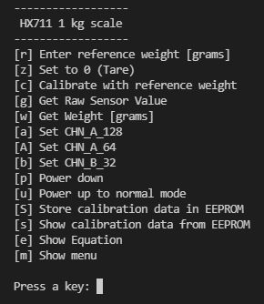
First we enter the reference weight in grams, then we set the scale to zero without any load, then we place the reference weight on the scale and finally we calibrate it by pressing key 'c'. When we now press 'w', we see the applied weight in grams.
The main program, is quite simple. Here only the part is shown, where the already in EEPROM stored calibration values are retrieved to initialize the scale.
  constexpr uint8_t ADDR_INIT_FLAG  = 0;
  constexpr uint8_t ADDR_REF_WEIGHT = ADDR_INIT_FLAG  + sizeof(uint8_t);
  constexpr uint8_t ADDR_V0         = ADDR_REF_WEIGHT + sizeof(int32_t);
  constexpr uint8_t ADDR_VREF       = ADDR_V0         + sizeof(int32_t);
  constexpr uint8_t ADDR_CHN_GAIN   = ADDR_VREF       + sizeof(int32_t);
  constexpr uint8_t EEPROM_END      = ADDR_CHN_GAIN   + sizeof(uint8_t);
  constexpr uint8_t EEPROM_SiZE     = EEPROM_END - ADDR_INIT_FLAG;

  void initScale()
  {
    // if the magic number is present, coefficients were stored in
    // EEPROM and the relevant values can be retrieved from it
    if (EEPROM.get(ADDR_INIT_FLAG, initFlagEeprom) == MAGIC_NBR)
    {
      int32_t v = 0;
      uint8_t chnGain = 0;
      EEPROM.get(ADDR_REF_WEIGHT, v);     myScale.set_wref(v);
      EEPROM.get(ADDR_V0, v);             myScale.set_v0(v);
      EEPROM.get(ADDR_VREF, v);           myScale.set_vref(v);
      EEPROM.get(ADDR_CHN_GAIN, chnGain); myScale.set_chnGain((CHN_GAIN)chnGain);
      myScale.calculateCoefficients();
    }
  }

  void setup()
  {
    Serial.begin(115200);
    initScale();
    showMenu();
  }

  void loop()
  {
    if(Serial.available())
    {
      doMenu();
    }
 }
Interested? Please download the entire program code. The zip-file contains the complete PlatformIO project.
My programming environment is not the native Arduino™ IDE but PlatformIO™ on top of Microsoft's Visual Studio Code™. This combination offers many advantages and allows a much better structuring of the code into several modules especially when we adopt The Object Oriented way.