4. User Interface
The user interface is a simple command line interface. The menu items are self-explanatory.
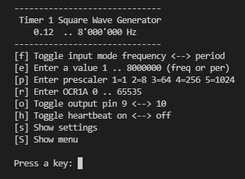
If not exact frequencies are required for a test, this generator can be quite useful. Since prescaler and register can also be manipulated directly via the CLI menu on the serial monitor and the calculated values are displayed, this deepens the understanding of the interaction of prescaler and register.
No wiring necessary
The user interface is a simple command line interface. The menu items are self-explanatory.
And this is how it looks in the program code:
  TCCR1A = 0;  // clear the register
  if (pin ==  9) TCCR1A = 1 << COM1A0;  // set output pin
  if (pin == 10) TCCR1A = 1 << COM1B0;
  TCCR1B = 0b00001001; // Prescaler = 001 = 1
  //             ^---
  //             | |
  //             | prescaler bits,
  //             WGM12 bit for CTC mode
  TIMSK1 = 0; // clear the register
But the most important thing is still missing. How must the bits of the prescaler and the value of the output compare register be set? For this we still need some definitions and formulas:
  prescaler:       3 least significant bits of TCCR1B = 0b00000xxx
                   stand for a divider of 1, 8, 64, 256, 1024 for fo
  compare value:   OCR1A (output compare register) contains values 0x0000 .. 0xFFFF

  fo               8'000'000 (half of fcpu)
  f                desired frequency in Hz
  T                desired period in seconds
  Tus              desired period in microseconds
  ocr              content of 16-bit register OCR1A

  f = fo / ((ocr + 1) * pre),  fo = 8'000'000 Hz and pre = 1, 8, 64, 256, 1024
  T = (ocr+1) * pre / fo

  ocr = fo / f / pre - 1
  ocr = T * fo / pre - 1
      = Tus * 8 / pre - 1

  If the value of ocr is greater than 0xFFFF, the next higher prescaler is taken

  The tables below show the resulting frequencies and periods for the possible
  prescalers and the ocr values 0x0000 and 0xFFFF.

                                 Resulting frequencies [Hz]
                --------------------------------------------------------------
  pre =         1            8            64           256          1024
                --------------------------------------------------------------
  ocr = 0x0000  8000000      1000000      125000       31250        7812.5
  ocr = 0xFFFF  122.0703125  15.25878906  1.907348633  0.476837158  0.11920929

                                 Resulting periods [us]
                --------------------------------------------------------------
  pre =         1            8            64           256          1024
                --------------------------------------------------------------
  ocr = 0x0000  0.125        1            8            32           128
  ocr = 0xFFFF  8192         65536        524288       2097152      8388608
With this knowledge we can now calculate the value for the 16-bit register OCR1A. To get the best accuracy, we convert the 32-bit integers of fo, freq and pre to floating point numbers, round the result and convert back to a 16-bit integer for the ocr value.
OCR1A = (uint16_t)(round( (double)fo / (double)pre / (double)freq - 1.0 ));
Interested? Please download the entire program code. The zip-file contains the complete PlatformIO project.
My programming environment is not the native Arduino™ IDE but PlatformIO™ on top of Microsoft's Visual Studio Code™. This combination offers many advantages and allows a much better structuring of the code into several modules especially when we adopt The Object Oriented way.